
Here you can add and manage your own camera models. System cameras (added by an administrator) are shown in the list but cannot be edited here.
Reads FOV, resolution, fps and power from an uploaded PDF as a suggestion to review – never fills in the form automatically.
Suggestion from PDF
Automatically extracted – always check against the datasheet before using the values. Click a field to transfer it to the form below.
PoE class: 802.3af (calculated automatically)
My recorders and servers
Your company's own NVR and server models, with your price. They can be selected on a recorder in the drawing tool together with the system models, and the price is carried over to the bill of materials.
You need active access to create signs. Get access
You need active annual access to use the camera register.
You have not purchased the service yet, or it has expired.
Annual Inspection is not yet included in your services.
With Annual Inspection you document the recurring inspection of existing installations in accordance with SSF 1060.
Room measurement (image analysis and mobile planning) is an add-on service. You need active access to it.
Room measurement (image analysis and mobile planning) is an add-on service. You need active access to it.
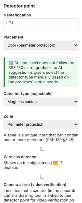
Detector point
The coverage is drawn on the plan (0° = to the right, clockwise). The defaults 90°, 12 m and 2.2 m are usual for wall mounting – follow the datasheet.
A zone is a unique input that can contain one or more detectors (SSF 130 §3.25).
Shown on the signal map (📶) if enabled. With an alarm grade, SSF 130 applies and the system must be wired. Wireless is only possible with Custom level.
Blank = calculated from commissioning.
Indicates that a camera (in the separate camera drawing tool) is linked to this detector point for video verification on alarm.
Zones
A zone is a uniquely defined input that can contain one or more detectors (SSF 130 §3.25).
| Zone | Detector points | Zone wiring and resistors |
|---|
Alarm areas
An alarm area groups zones that are set/unset together (SSF 130 §5.24–§5.27).
Terminal block
The terminals are numbered in pairs as on an alarm terminal block (1–2, 3–4 …). Click a terminal to assign the pair the supply (+ and −) or a zone – SSF 130 §3.23. Select the terminal block under Product and the number of terminals follows it.
Siren / sounder
With an alarm grade, the system must be wired.
Radio range extender
Wireless system
Wireless applies to Custom level – with an alarm grade the system is wired (SSF 130).
Devices and signal
Estimate: the manufacturer's free-field range minus the walls' attenuation by wall type (right-click a wall; Standard = Attenuation/wall). Good ≥ 15 dB margin, weak 6–15 dB, out of range below 6 dB. Confirm with the manufacturer's signal test during installation.
| Device | Product | To | Walls | Margin |
|---|
Batteries
| Device | Battery | Service life | Replace by |
|---|
Smoke/heat detector
Enter according to the manufacturer's instructions for the detector in question – there is no built-in default value, you enter it based on the selected product.
User guide – Access control
Room
🏠 Rooms from walls creates rooms from the closed walls (the same method as the network tool). If a room is missing: straighten the walls so that the corners meet, or draw the room yourself with the Room tool – click the corners and double-click to close.
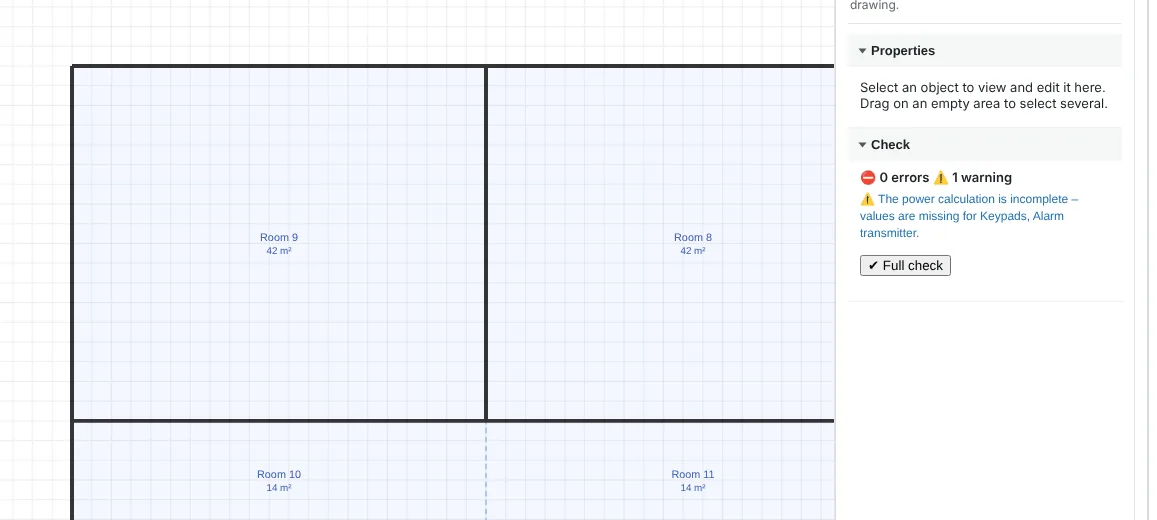
Right-click a room for name and type. The type controls the guide's suggestions: volumetric protection in all types except WC/shower and Other. Rooms under 4 m² get the type Other – SSF 130 exempts WC/shower and windowless spaces under 4 m² in alarm grades 3–4.
If the sheet is linked to a building, the rooms are shared with the other tools: a room drawn in the network tool is visible here and vice versa. The room type is specific to each tool.
Step by step
1 Drawing: give the drawing a name and add the floor plan – image, PDF or a DXF/DWG (beta) – or select Draw without floor plan. 2 Scale: click two points with a known distance. 3 Walls and rooms: draw the walls (or let AI read them from the floor plan), doors and windows, and create the rooms.
4 Alarm grade and system. 5 Detector points: Suggest detector points and move them to suit the room. 6 Zones. 7 Sounders and control panel. 8 Power and batteries. 9 Access control system (optional). 10 Check and binder.

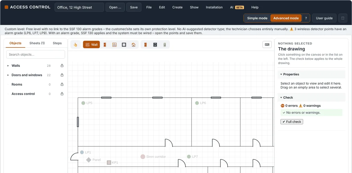
Select works as in advanced mode: drag an object to move it, drag on an empty area for a selection box, Shift+click for several, Delete removes the selected items and Ctrl+D copies them. The step lock also applies to the selection – only what belongs to the step is selected.
On a touchscreen, one finger draws and moves; one finger on an empty area in Select pans, and two fingers pinch to zoom and pan the canvas.
Access control
The access control system is drawn with door environments (click a door), controllers and power supply units. The door is connected to the nearest controller with space left and the controller to the nearest power supply unit – change this in the panel. In the intruder alarm, the layer is switched on with 🚪 Access control; Access control in the hub is the same tool with the same drawings and subscription.
With the add-on AI design – intruder alarm, AI → Finish the access control lays out the door environments in one go: at the external doors and the doors to IT and OT spaces (preselected, MCFFS 2026:11 chapter 5) or the doors you choose. The lock is locked when de-energised (fail secure) and external doors that are escape routes get a mechanical exit (EN 179/1125). Readers from the system's range, with a keypad where the alarm is set and unset with a card in alarm grade 3–4. The controller is the alarm control panel when it is the system's panel (integrated access control), otherwise door or sub-controllers by the number of doors. The power supply unit is chosen by the power budget and the wiring views are laid out from the terminal templates. What is already there is kept and everything is undone in one step.
The checks: an escape route requires a lock that opens on power failure with emergency opening, or a mechanical exit according to SS-EN 179/1125, and S1/S2 – S3/S5 require authorisation from both sides (SSF 3523). An external door with fail safe gives a warning. Setting/unsetting with a card requires a PIN code in alarm grades 3–4 and decision logic within an alarm-monitored area in alarm grades 2–4. A lock bypass is not permitted in alarm grades 2–4 and requires at least class 3/S3 in alarm grade 1 (SSF 130 5.22–5.27). S3/S5 require tamper protection.
The power budget per power supply unit sums the quiescent current for controllers, readers and locks and adds the operating current for the locks that may be activated at the same time. If the access control system is powered from the alarm's power supply, the tool gives a warning (SSF 130 5.9.6).
SS-EN 60839-11-1 (security grade) is not checked, and the authority requirements for evacuation – BBR and the fire protection documentation – always take precedence.
Wiring view
🔌 Wiring view (in the panel of the door, controller, detector point and siren) draws the device's terminals according to the manufacturer's installation instructions with reader, lock, door contact, exit button, alarm bypass and power supply unit alongside, and the wiring between the terminals. The door controller is suggested from the controller, the reader and the lock from the door's choices.
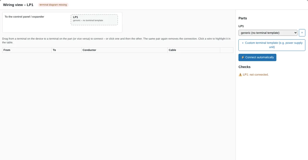
The connection is first made according to the manufacturer's wiring example. If the part has its own terminal template (e.g. HID, Idesco, Salto, Pando or ASSA's Hi-O lock), the terminals are paired by function and label; otherwise a generic part is drawn with the example's text. Click a terminal on the device and then a terminal on the part to connect it yourself; conductor colour and cable are entered in the table.
The check warns about unconnected terminals, wrong function or polarity, voltage outside the part's range, excessive load on the output and Hi-O locks on devices without CAN. Templates marked partially verified have terminals that only appear in the manual's figures – check them against the manufacturer's instructions. If there is no terminal template for the system (e.g. Scantron, Omnis, Entro, Nedap), the manufacturer's installation manual is needed.
The wiring views are included in the binder and can be printed individually. Keypads are added as modules in the control panel's board view.
Drag from a terminal to a terminal on the other part to connect them – drag the same way again to remove the connection. Click–click also works.
If a power supply unit, keypad or module is missing from the templates: + Custom terminal template. Enter model, voltage, maximum current and the terminals (e.g. L, N, PE, +12V, 0V, BAT+, BAT−, FEL). The function is guessed from the label and can be specified with an equals sign (FEL = ovrigt). The template is saved for the company and can be deleted with ×.
The terminal's function decides what can be connected: detectors and zones on zone or loop terminals, modules and keypads on the bus, sounders on the sounder terminals. The modules must be of the panel's make. In the panel's board view each module and keypad gets a bus (the panel's bus terminals) and an address. The same address twice on the same bus is flagged, and the bus with its addresses is included on the connection card. The address is set on the module according to the manufacturer's instructions.
Wired: control panel and modules
🎛️ Control panel and modules: the catalogue has wired control panels from Aritech, Honeywell, Texecom, Bosch, Risco and Inim, and the hybrid control panels Vanderbilt SPC, DSC Neo, Ksenia lares 4.0 and Ajax Superior Hub Hybrid. Modules (zone expanders, outputs) are added with quantity.
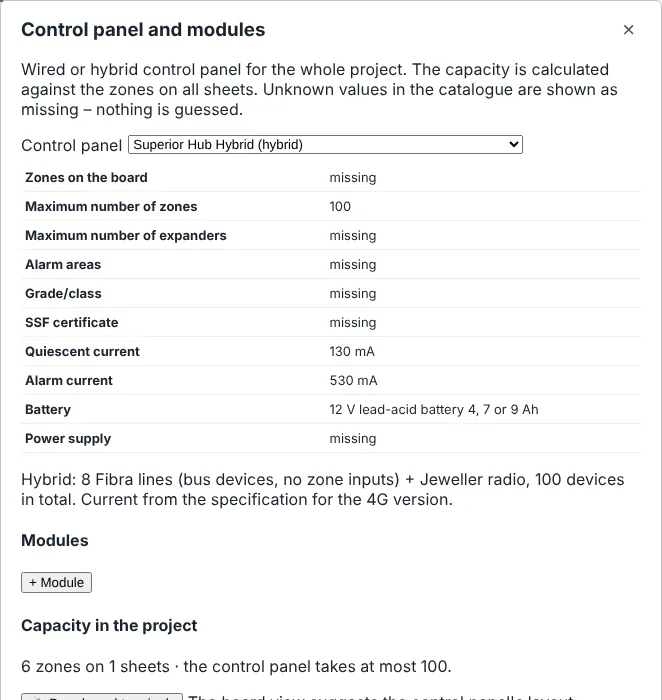
Capacity is calculated for the whole project: the zones on all sheets against the inputs on boards and modules and against the control panel's maximum number. The control panel is selected once – the other sheets inherit it. Values missing from the catalogue are shown as missing; nothing is guessed.
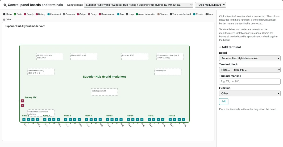
The board view (🔌 Boards and terminals) suggests the control panel's board layout, and the connections are included in the wiring diagram and the binder.
All wired control panels in the catalogue have a board layout from the manufacturer's manual. Where the manual only has a picture of the board without text (for example Aritech Everon and the zone terminals on Risco LightSYS 2), the board's parts are shown but not all terminals – add them with Add terminal and the label printed on the board. The positions of the terminal blocks on the board are approximate.
If a zone terminal block has no terminals (for example SPC5350/6350), the board view has the button Add Z1–Zn. Sounders and junction boxes whose tamper goes to the control panel's tamper input are connected to the tamper terminal (for example TR or AUX TMP).
The menu bar, the side panel and the status bar
Advanced mode has the menu bar File, Edit, Create, View, Installation, AI and Help with all tools – including signal and siren maps, attenuation, wall types and smoke/heat. The letters on the keyboard select tools (W wall, L detector point …); ? shows all keyboard shortcuts.
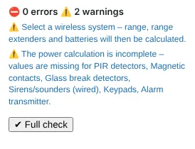
To the right of the canvas is the side panel, as in the camera tool. Properties shows what you have selected – detector point, terminal, siren, smoke/heat detector, range extender, room or access control object – so that the panel does not cover the drawing. Check summarises errors and warnings for the sheet with a button to the full check. Click the heading to collapse a section; the tool remembers which ones are open.
The status bar above the canvas says what is happening: what is selected, what a click does and what went wrong.
Select, move and multiple selection
With Select (V) you click an object to edit it, and drag it to move it – detector points, terminals, sirens, smoke/heat detectors, range extenders, the control panel and the access control system's objects. Doors and windows are dragged along the wall.
Drag on an empty area for a selection box: everything inside the box is selected (walls when both ends are inside). Shift+click adds or removes an object from the selection. Drag a selected object and all selected items move together.
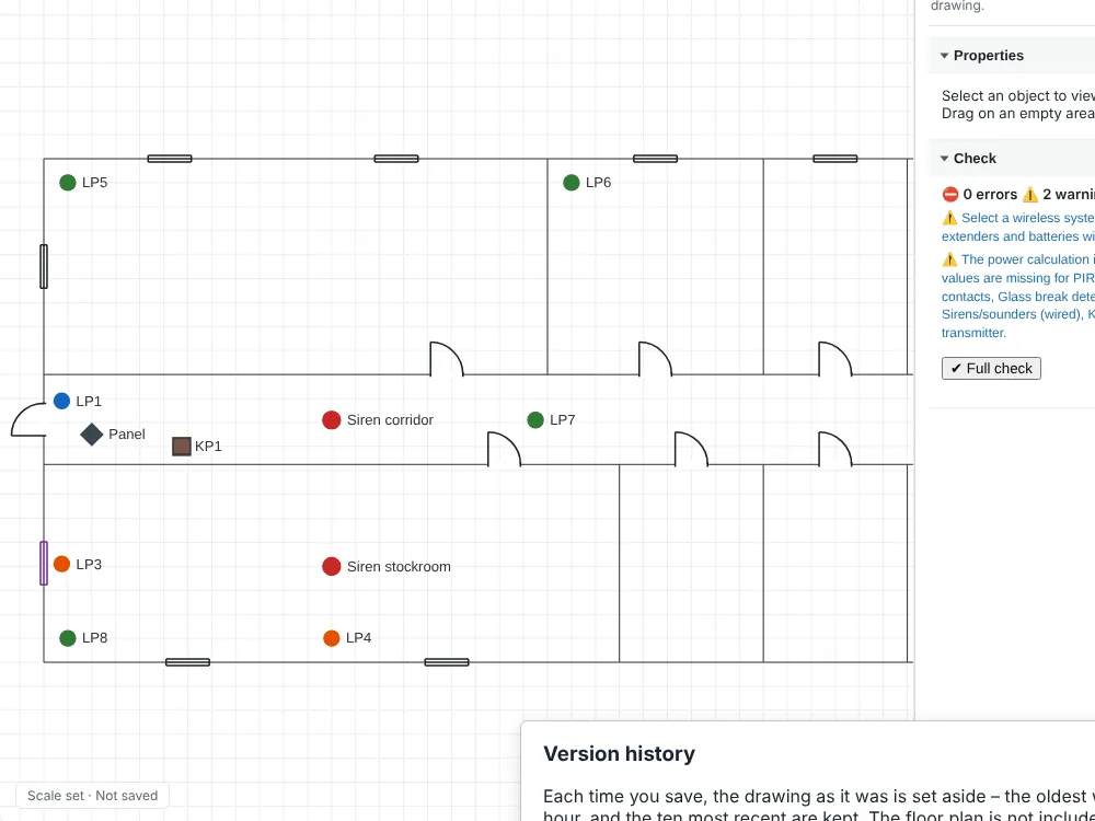
Delete removes all selected items at once – Ctrl+Z undoes the whole deletion in one step. Ctrl+D makes a copy of the selected items next to the originals (the control panel is not copied, there is only one). Esc deselects.
Right-click an object for its menu. Move in the menu: then click where the object should go.
Version history
Each time a saved drawing is saved again, the previous state is set aside as a version – the oldest within half an hour is kept, and the ten most recent are saved. File → 🕓 Version history shows them with the time, who saved and what the drawing contained. Restore asks first; the state you leave becomes a version of its own, so you can always go back. The floor plan is not included in the versions.
The drawing as PDF
File → 📄 Export PDF gives the sheet as a PDF in A3 or A4 landscape (Paper size in the File menu) with a title block according to SS 455 12 01: installation company, premises, alarm grade, drawing type, status, drawn by, date, revision, scale, document reference and sheet. The drawing is set to the nearest standard scale when the scale is set. Installation company and premises are taken from the binder details. 👁 Preview document shows the PDF first, with Download and Print.
During the trial period the watermark TEST – Kamerakollen is burned into the page; in open beta the PDF gets beta marking.
DXF/DWG and AI walls (beta)
File → 📐 Import DXF/DWG (beta) reads the walls from a CAD drawing via the AI server. The tool shows which layers became walls and lets you correct the list. The scale is set exactly from the file's millimetres and the canvas is adjusted to the drawing. Existing walls, doors and windows are replaced – Ctrl+Z undoes the import in one step.
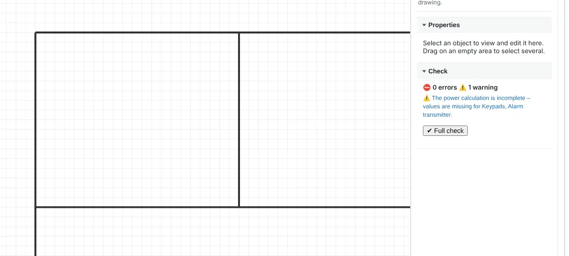
AI → 🪄 Run AI on walls reads walls, doors and windows from the uploaded floor plan (image or PDF) and places them on top. The result is a BETA – review the walls, straighten them and correct the wall types before you calculate radio and sirens.

Room
🏠 Rooms from walls creates rooms from the closed walls (the same method as the network tool). If a room is missing: straighten the walls so that the corners meet, or draw the room yourself with the Room tool – click the corners and double-click to close.
Right-click a room for name and type. The type controls the guide's suggestions: volumetric protection in all types except WC/shower and Other. Rooms under 4 m² get the type Other – SSF 130 exempts WC/shower and windowless spaces under 4 m² in alarm grades 3–4.
If the sheet is linked to a building, the rooms are shared with the other tools: a room drawn in the network tool is visible here and vice versa. The room type is specific to each tool.
Access control
The access control system is drawn with door environments (click a door), controllers and power supply units. The door is connected to the nearest controller with space left and the controller to the nearest power supply unit – change this in the panel. In the intruder alarm, the layer is switched on with 🚪 Access control; Access control in the hub is the same tool with the same drawings and subscription.
With the add-on AI design – intruder alarm, AI → Finish the access control lays out the door environments in one go: at the external doors and the doors to IT and OT spaces (preselected, MCFFS 2026:11 chapter 5) or the doors you choose. The lock is locked when de-energised (fail secure) and external doors that are escape routes get a mechanical exit (EN 179/1125). Readers from the system's range, with a keypad where the alarm is set and unset with a card in alarm grade 3–4. The controller is the alarm control panel when it is the system's panel (integrated access control), otherwise door or sub-controllers by the number of doors. The power supply unit is chosen by the power budget and the wiring views are laid out from the terminal templates. What is already there is kept and everything is undone in one step.
The checks: an escape route requires a lock that opens on power failure with emergency opening, or a mechanical exit according to SS-EN 179/1125, and S1/S2 – S3/S5 require authorisation from both sides (SSF 3523). An external door with fail safe gives a warning. Setting/unsetting with a card requires a PIN code in alarm grades 3–4 and decision logic within an alarm-monitored area in alarm grades 2–4. A lock bypass is not permitted in alarm grades 2–4 and requires at least class 3/S3 in alarm grade 1 (SSF 130 5.22–5.27). S3/S5 require tamper protection.
The power budget per power supply unit sums the quiescent current for controllers, readers and locks and adds the operating current for the locks that may be activated at the same time. If the access control system is powered from the alarm's power supply, the tool gives a warning (SSF 130 5.9.6).
SS-EN 60839-11-1 (security grade) is not checked, and the authority requirements for evacuation – BBR and the fire protection documentation – always take precedence.
Wiring view
🔌 Wiring view (in the panel of the door, controller, detector point and siren) draws the device's terminals according to the manufacturer's installation instructions with reader, lock, door contact, exit button, alarm bypass and power supply unit alongside, and the wiring between the terminals. The door controller is suggested from the controller, the reader and the lock from the door's choices.
The connection is first made according to the manufacturer's wiring example. If the part has its own terminal template (e.g. HID, Idesco, Salto, Pando or ASSA's Hi-O lock), the terminals are paired by function and label; otherwise a generic part is drawn with the example's text. Click a terminal on the device and then a terminal on the part to connect it yourself; conductor colour and cable are entered in the table.
The check warns about unconnected terminals, wrong function or polarity, voltage outside the part's range, excessive load on the output and Hi-O locks on devices without CAN. Templates marked partially verified have terminals that only appear in the manual's figures – check them against the manufacturer's instructions. If there is no terminal template for the system (e.g. Scantron, Omnis, Entro, Nedap), the manufacturer's installation manual is needed.
The wiring views are included in the binder and can be printed individually. Keypads are added as modules in the control panel's board view.
Drag from a terminal to a terminal on the other part to connect them – drag the same way again to remove the connection. Click–click also works.
If a power supply unit, keypad or module is missing from the templates: + Custom terminal template. Enter model, voltage, maximum current and the terminals (e.g. L, N, PE, +12V, 0V, BAT+, BAT−, FEL). The function is guessed from the label and can be specified with an equals sign (FEL = ovrigt). The template is saved for the company and can be deleted with ×.
The terminal's function decides what can be connected: detectors and zones on zone or loop terminals, modules and keypads on the bus, sounders on the sounder terminals. The modules must be of the panel's make. In the panel's board view each module and keypad gets a bus (the panel's bus terminals) and an address. The same address twice on the same bus is flagged, and the bus with its addresses is included on the connection card. The address is set on the module according to the manufacturer's instructions.
Wired: control panel and modules
🎛️ Control panel and modules: the catalogue has wired control panels from Aritech, Honeywell, Texecom, Bosch, Risco and Inim, and the hybrid control panels Vanderbilt SPC, DSC Neo, Ksenia lares 4.0 and Ajax Superior Hub Hybrid. Modules (zone expanders, outputs) are added with quantity.
Capacity is calculated for the whole project: the zones on all sheets against the inputs on boards and modules and against the control panel's maximum number. The control panel is selected once – the other sheets inherit it. Values missing from the catalogue are shown as missing; nothing is guessed.
The board view (🔌 Boards and terminals) suggests the control panel's board layout, and the connections are included in the wiring diagram and the binder.
All wired control panels in the catalogue have a board layout from the manufacturer's manual. Where the manual only has a picture of the board without text (for example Aritech Everon and the zone terminals on Risco LightSYS 2), the board's parts are shown but not all terminals – add them with Add terminal and the label printed on the board. The positions of the terminal blocks on the board are approximate.
If a zone terminal block has no terminals (for example SPC5350/6350), the board view has the button Add Z1–Zn. Sounders and junction boxes whose tamper goes to the control panel's tamper input are connected to the tamper terminal (for example TR or AUX TMP).
Keyboard shortcuts
| Ctrl+Z / Ctrl+Y | Undo / redo |
|---|---|
| Ctrl+S | Save |
| Delete | Delete the selected items (one undo step), or the selected door/window, room or access control object |
| Ctrl+D | Duplicate the selected items |
| Shift+click | Add to or remove from the selection |
| Drag on empty area | Selection box (in Select) |
| Esc | Cancel what is being drawn or moved, deselect |
| + − | Zoom; the mouse wheel zooms at the pointer |
| Space + drag | Pan |
| Two fingers | Pinch to zoom and pan (touchscreen) |
| Double-click | Close the room you are drawing |
| Right-click | Menu for the object under the pointer |
| ? | Keyboard shortcuts |
The tool's suggestions and checks do not replace an authorised alarm installer's design and testing according to SSF 130.
The detector suggestion is a rule-based starting point based on SSF 130 and does not replace the assessment of an authorised alarm installer. Always adjust based on the actual conditions of the premises.
Drawing not found.
[kdbrand_ritverktyg][kdbrand_provning][kdnat_ritverktyg]Installation mode – testing, self-inspection, test images and as-built document – is an add-on service to the drawing tools. You need active access to it.
Installation mode – testing, self-inspection, test images and as-built document – is an add-on service to the drawing tools. You need active access to it.
Installation mode – testing, self-inspection, test images and as-built document – is an add-on service to the drawing tools. You need active access to it.
Installation mode – testing, self-inspection, test images and as-built document – is an add-on service to the drawing tools. You need active access to it.
NIS2 is coming soon.
A separate service for the Cybersecurity Act (NIS2) and your customers' security systems: whether the customer is covered, the camera, alarm and access control systems against the MCF regulations with an action plan, audit, incidents with deadlines to NCSC and IMY, and an annual report to management.
The service cannot be ordered yet. When it is ready, you will find it under Order services.
NIS2 is coming soon.
A separate service for the Cybersecurity Act (NIS2) and your customers' security systems: whether the customer is covered, the camera, alarm and access control systems against the MCF regulations with an action plan, audit, incidents with deadlines to NCSC and IMY, and an annual report to management.
The service cannot be ordered yet. When it is ready, you will find it under Order services.
NIS2 is coming soon.
A separate service for the Cybersecurity Act (NIS2) and your customers' security systems: whether the customer is covered, the camera, alarm and access control systems against the MCF regulations with an action plan, audit, incidents with deadlines to NCSC and IMY, and an annual report to management.
The service cannot be ordered yet. When it is ready, you will find it under Order services.
NIS2 is coming soon.
A separate service for the Cybersecurity Act (NIS2) and your customers' security systems: whether the customer is covered, the camera, alarm and access control systems against the MCF regulations with an action plan, audit, incidents with deadlines to NCSC and IMY, and an annual report to management.
The service cannot be ordered yet. When it is ready, you will find it under Order services.
🏢 Your company details
Your account has no company details. Enter them once here – they are used in all orders below, saved on the account and can then only be changed by us.
Company name Demo – Kamerakollen
📐 Camera drawing tool
Draw walls, plan camera placement and see coverage areas in 2D and 3D.
Request invoice (company)
We will send you an invoice. The service is activated when the invoice is approved.
🔔 Intruder alarm drawing tool
Draw walls, place detector points and get AI suggestions for detector type based on alarm grade (SSF 130).
Request invoice (company)
We will send you an invoice. The service is activated when the invoice is approved.
🔌 Network installation
Draw network outlets and access points, with IP lists and wiring diagrams.
Request invoice (company)
We will send you an invoice. The service is activated when the invoice is approved.
🔥 Fire alarm drawing tool
Design automatic fire alarm systems according to SBF 110:8 – detectors, loops, sounders, orientation drawings and requirement checks.
Request invoice (company)
We will send you an invoice. The service is activated when the invoice is approved.
Coming soon
This is what we are working on. These services cannot be ordered yet – they will appear above when they are ready.
🛡️ NIS2 Coming soon
The Swedish Cybersecurity Act (NIS2) for your customers' security systems: whether the customer is covered, the camera, alarm and access control systems against MCF's regulations with an action plan, supplier documentation and a contract annex, a system inventory, incidents with deadlines to the NCSC and IMY, and an annual report to management. A service of its own – no other subscription required.
🤖 AI design Coming soon
Add-on to the camera drawing tool: answer a few questions and the zones are added per room and around the house, and the AI places the cameras and completes the installation – switch, recorder, cables and IP addresses. Monthly fee that follows the main subscription.
🤖 AI design – network Coming soon
Add-on to the network tool: Complete the data network – outlets and access points by room type and coverage, distribution, cable containment, cables within 90 m, switches and patch panels from the catalogue, patching, VLAN plan and IP addresses in one go. Monthly cost that follows the main subscription.
🤖 AI design – fire alarm Coming soon
Add-on to the fire alarm tool: room names and room types from the floor plan, so the requirements per space come along directly – and soon Finish the installation with control panel, loop cards, power supply and battery. Monthly cost that follows the main subscription.
🤖 AI design – intruder alarm Coming soon
Add-on to the intruder alarm tool: room names and room types from the floor plan, so the suggested detectors follow the rooms – and soon Finish the installation with detectors by grade, control panel and expanders, perimeter protection and door environments. Monthly cost that follows the main subscription.
Help and services
What each tool does and how to get started. Here you can also see what is available in the other services.
Help with your panel
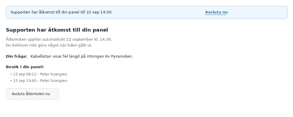
If something is not right in your drawings, registers or signs, you can ask us to look at it in your own panel. You describe what you want help with and choose how long the access should last – 1, 3, 7, 14 or 30 days.
Click Request help in the hub. If the help is chargeable, the price is shown in the form and you approve it with a separate tick before the request can be sent. The price you approve is fixed on the case – a later price change never applies retroactively.
The price may have been agreed specifically for you – what is shown in the form is what applies to your account.
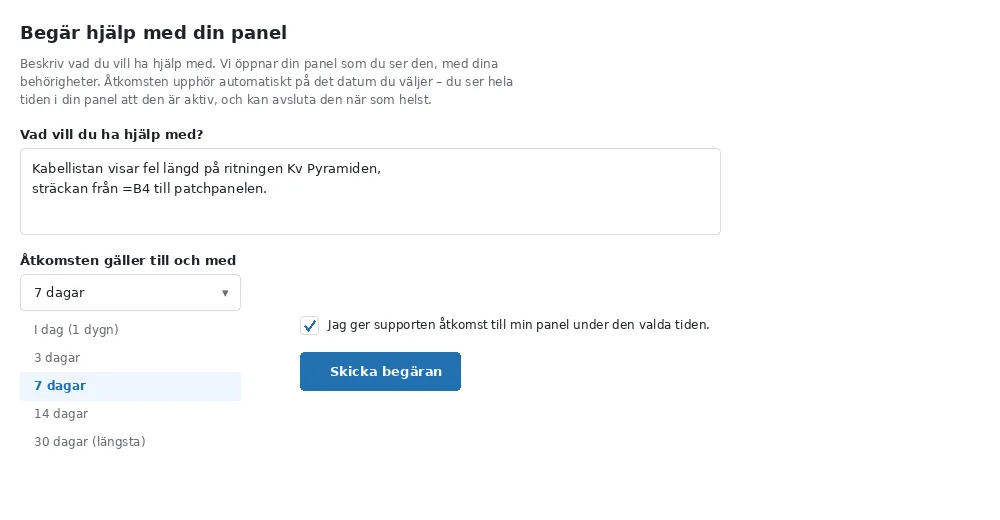
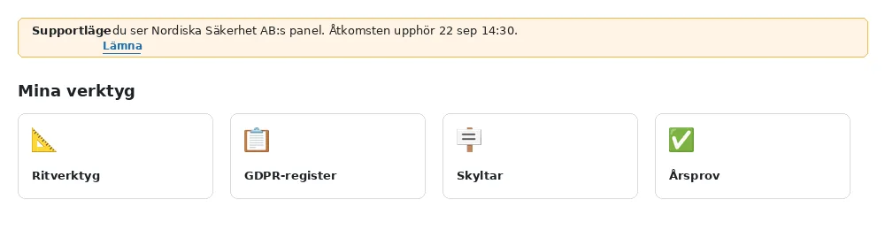
Three things always apply: access ends automatically when the time has run out, you can see in your panel that it is active and can end it at any time, and every visit is logged with the time and name so that you can see what has happened. We can see and change what you see, but can never change your password or access your payment details.
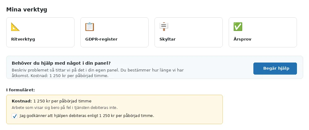
Your services
Drawing tool Draw camera installations on a floor plan and get documentation according to SS 455 12 01.
- Import a floor plan as a PDF or image and calibrate the scale.
- Place cameras with the right lens and see the coverage directly on the drawing.
- DORI analysis: the level of detail the camera gives at different distances.
- Route cables, calculate the PoE budget and storage requirements.
- Export the installation drawing and summary as a PDF with text fields.
Good to know: Calibrate the scale before you place anything – all analysis is based on it.
Camera types Camera models with technical data, as a basis for drawings and quotes.
- Models from Axis, Hikvision, Dahua, Hanwha, Bosch, Avigilon and Pelco.
- Resolution, lens, power consumption and housing.
- Mark the company's favourite models for quicker selection.
Good to know: Models marked as favourites appear at the top when you choose a camera in the drawing tool.
Price list Your own purchase prices per camera model, as a basis for quotes and bills of materials.
- Enter your price per model – if the field is left empty, the list price is used.
- Your own lists to collect the models you use most often.
- The prices are carried over to the drawing tool's bill of materials.
Network & rack Document the rack cabinet: where the equipment is and how it is patched.
- Place switches, patch panels, NVR, NAS, router and UPS in the cabinet.
- Drag and drop to move – the position numbers are recalculated automatically.
- Patch port by port, including switch to switch as a trunk.
- Installation drawing and connection diagram according to SS 455 12 01 Appendix O.
- IP plan and VLAN per device, with a check for duplicate addresses.
- PoE load per switch against the specified budget.
- Cable list with labelling to take out on site.
Good to know: Click a switch in the rack view to open all ports in a large format – that is where patching is fastest.
Inspection log The camera system inspection log in digital form, with a QR sticker on the recorder (SSF 1060 10.7).
- One log per installation, with installation company, certificate, system owner and caretaker.
- Each person gets their own 6-digit code – without a code, the QR page shows nothing.
- Inspections, fault signals with cause and action, operational disruptions, service visits and changes – nothing can be deleted.
- Works without a signal – the entry is sent when the connection is back.
Good to know: Sold per installation for 1, 3 or 5 years.
Intruder alarm drawing tool Draw intruder alarms with detectors, control panel and zones.
- Place detectors and see coverage areas.
- Zone division and cable routing.
- Documentation according to SSF 130.
- File → Documentation package (zip): PDF, the cable and battery lists and DXF in one file.
- The AI design add-on: Finish the installation – perimeter protection around the building, models by the alarm grade, control panel and expanders, terminals and battery in one go.
Access control Door environments for access control systems: readers, locks, door contacts and wiring.
- Draw door environments on the same floor plan as the alarm.
- Wiring diagram per door.
- The AI design add-on: Finish the access control – door environments, readers, locks, controllers and power supply units in one go.
Good to know: Included in the subscription for Intruder alarm drawing tool.
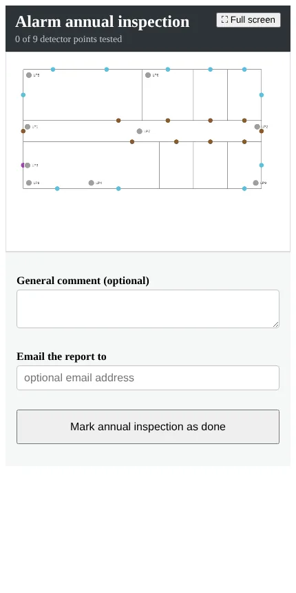
Alarm annual inspection Annual functional inspection of the intruder alarm, documented and signed.
- Report per installation with detectors and zones from the drawing.
- History of previous inspections.
Good to know: Included in the subscription for Intruder alarm drawing tool.
Inspection log The intruder alarm inspection log in digital form, with a QR sticker on the control panel (SSF 130 8.9 and B1.8).
- One log per installation, with the details from the installer's certificate.
- Everyone named on the installer's certificate gets their own 6-digit code – without a code, the QR page shows nothing.
- Alarm activations, fault signals with cause and action, testing, service and unsetting – nothing can be deleted, corrections become new entries.
- The annual inspection in the alarm tool is entered automatically.
- Works without a signal – the entry is sent when the connection is back.
- Own ambition: hand the log over to the owner, who manages the codes and the extension in the installation portal.
Good to know: Sold per installation for 1, 3 or 5 years. If a sticker has gone astray – create a new QR link and the old one stops working.
Fire alarm drawing tool Design automatic fire alarm systems according to SBF 110:8 – detectors, loops, sounders and orientation drawings.
- Automatic detector placement based on room geometry and ceiling height.
- Zones, loops and control panels with a requirements check.
- Orientation drawings and installer's certificate data.
- The AI design add-on: Finish the installation – control panel, loops, battery and power supply in one go.
Fire alarm testing Monthly check, quarterly test and annual maintenance of the fire alarm according to SBF 110:8, with an inspection log.
- The quarterly test rotates the zones so that every detector is tested during the year.
- The Due tab shows what to test next.
- The inspection log with all tests and deviations.
- Works without coverage – tests are sent when the connection is back.
Good to know: Included in the Fire alarm drawing tool subscription.
Network installation Document network installations with documents according to SS 455 12 01.
- Outlets and access points on a floor plan, with estimated Wi-Fi coverage.
- Cable runs with automatic length and a warning at the 90-metre limit.
- Installation drawing of the racks and distribution list per switch port.
- Cable and containment list with material quantities.
- Test report with length check and pair check.
- VLAN plan, and the IP, cable and distribution lists as CSV.
- The AI design add-on: Finish the data network in one go, with the room names from the floor plan.
- File → Documentation package (zip): PDF, the lists as CSV, image and DXF in one file.
- Multiple sheets for installations spanning several floors.
Good to know: Calibrate the scale before you draw anything – without it, lengths cannot be calculated and the cable list shows no measurements.
Network & rack The racks, equipment and switch ports of a network drawing, gathered in one place.
- Each rack with height, occupied rack units and number of devices.
- The equipment with make, ports, PoE, IP address and position in the rack.
- Mounting drawing per rack and distribution list per switch port according to SS 455 12 01.
- The connection diagram for printing.
Good to know: The equipment is changed in Network installation under Equipment – here you see the result.
Other services not included in your services
Camera signs Create camera signs according to IMY's template, with an information page per site.
- Signs in A3, A4, A5, A6 or a custom size – portrait and landscape.
- Your own information page per site with a QR code, in your own layout.
- Contact form where the public can exercise their rights.
- Swedish, English or both on the same sign.
- Export a register of all surveillance locations ahead of supervision.
Good to know: Signs are sold per site – each licence gives one site one year. If you have several entrances with the same details, use Copy instead of filling in everything again.
🔒 Open the tool Read more about the service 📖 Read the user guide
Surveillance register The documentation required by the Swedish Camera Surveillance Act and the GDPR.
- Register of video surveillance according to IMY's guidance.
- Legitimate interest assessment with needs, risks and conclusion.
- Assessment of whether a DPIA is needed.
- Checklist before commissioning.
Good to know: If you have both the register and the signs, the purpose can be taken from the register to the sign, so that they always say the same thing.
🔒 Open the tool Read more about the service
Annual inspection Annual functional inspection of the camera system, documented and signed.
- Report per installation with checkpoints.
- Carried out on a mobile on site – also works without coverage.
- Photos and remarks per camera.
- A finished report as a PDF to hand over to the customer.
Good to know: Add the annual inspection to your phone's home screen – it then works like an app on site.
🔒 Open the tool Read more about the service
Image analysis Measure rooms, angles and DORI coverage from an image from an existing camera.
- Upload a snapshot from the camera.
- Enter the mounting height and camera model, or a known measurement in the image.
- Get the room's dimensions and the camera's coverage as a basis for the drawing.
Good to know: Add-on to the drawing tools – requires an active main subscription.
🔒 Open the tool Read more about the service
Mobile planning Measure the rooms on site with your phone's camera and get them as a floor plan straight away.
- Walk around the room and point out the corners with your phone (AR where supported).
- Wall mode for rooms where the corners are hidden by furniture.
- The rooms appear in the drawing tool, ready for placing cameras.
Good to know: Add-on to the drawing tools – requires an active main subscription.
🔒 Open the tool Read more about the service
NIS2 documentation Documentation under the Swedish Cybersecurity Act (NIS2) for customers who are covered – one per customer.
- Whether the customer is covered, as an essential or important entity, and which supervisory authority applies.
- The camera, alarm and access control systems against MCF's regulations, with an action plan.
- Supplier documentation, contract annex, system inventory and annual report to management.
- Preparations and deviations for security audits and scans (MCFFS 2026:12).
- The equipment is taken from the drawings, with the support period from the catalogue.
Good to know: The documentation is shared with colleagues in the same company.
🔒 Open the tool Read more about the service
Is the customer covered? Quick check of whether a customer is covered by the Swedish Cybersecurity Act – nothing is saved.
- Choose the sector and enter the number of employees, turnover and balance sheet total.
- The assessment shows essential, important or probably not covered, with the reasons.
- Create documentation for the customer with the answers filled in when needed.
Good to know: The assessment is guidance – it is the customer who decides whether it is covered.
🔒 Open the tool Read more about the service
Incidents All customers' open incidents with the deadlines to the NCSC and IMY.
- Early warning within 24 hours, incident notification within 72 hours and final report within one month.
- Personal data breaches to IMY within 72 hours.
- Nearest deadline at the top, overdue steps marked.
🔒 Open the tool Read more about the service
Actions All customers' open actions from the action plans, overdue first.
- Action, owner, due date and status per customer.
- Show only the overdue ones when the list is long.
- Deviations from security audits and scans are included.
- Click the check to open it in the customer's documentation.
🔒 Open the tool Read more about the service
My installations The company's delivered installations in all tools, and what the customer sees under My installations. Available as a tab next to Tools.
- Enter the customer's email under Installation → Handover. The customer is invited to the installation portal when you hand over.
- When you hand over, the browser creates the handover report and the as-built document (the drawing, Rev B) and saves them for the customer – nothing to upload by hand.
- The customer sees the documents, the inspection log and your contact details. The photos from the testing stay with the company.
- ✏️ Edit in … opens the drawing directly in the right drawing tool for changes and additions – with an active service for the tool. The installation is reopened; hand over again when you are done and the customer gets the new documents.
Good to know: The telephone number the customer sees is the company telephone under My account.
🔒 Open the tool Read more about the service
Company and offices Offices for larger companies: each office only sees its own documentation and that of linked offices. Only for the company administrator.
- Create the offices and place the accounts – once the first office exists, offices apply to the whole company.
- Link two offices so that they see and edit each other's documentation, in both directions.
- Documentation stays with the office when someone changes office or leaves.
- A project manager, designer or technician from another office is added to a single drawing with Add person in the drawing tool.
- Company details, catalogues, price lists, templates and the customers in the installation portal are shared by all offices.
Good to know: As administrator you see no documentation that has not been shared with you – only the number per office.
🔒 Open the tool
Can't find the answer?
Get in touch via the contact form and we will help.
Hello Demo
My services
- 📐 Camera drawing tool valid until 3 November 2027
- 🔔 Intruder alarm drawing tool valid until 3 November 2027
- 🔌 Network installation valid until 3 November 2027
- Fire alarm drawing tool valid until 3 November 2027
Two-step verification
Required for your account – not enabled yet
Two-step verification is completed at the next login. If you have chosen an authenticator app, the QR code is shown there.
My details
Name: Demo
Email: demo@kamerakollen.invalid
Company: Demo – Kamerakollen
🔒 The company name and company registration number are used in your orders and cannot be changed here. If something needs changing – contact us.
Aggregated industry statistics
We compile de-identified statistics on how video surveillance is designed in Sweden, and may publish them as industry overviews. Only category data is included — never address, location description, contact details, free text or uploaded material, and never figures for groups so small that anyone can be identified.
Terms
You have accepted the current terms.
| Document | Version | Accepted |
|---|---|---|
| Terms of use | 1.3 | 2026-10-21 07:12 |
| Data processing agreement | 1.1 | 2026-10-21 07:12 |
The drawing tools
Choose how the tools open. You can always switch with the button in the top right of the tool – the choice is saved here and follows you to other computers.
Storage
252.0 KB of 2.0 GB used (0 %).
Language
The language for the tools, the hub and the emails we send you. Your choice is saved on your account.
Delete my account
You can request that your account and the personal data we process about you be deleted. The request goes to us directly — you do not need to send an email.
Before you request deletion, bear in mind that:
- An ongoing subscription does not end because the account is deleted. If you have an agreement, it needs to be cancelled separately.
- Under the Swedish Bookkeeping Act we must keep invoicing records for seven years, even after deletion.
- Documentation belonging to an operator is not deleted if you are only the person who entered it. Contact us and we will sort out what applies.
- We first suspend the account. You will then no longer be able to log in, but the content remains for 14 days. If you change your mind during that time, get in touch with us and we will reopen the account.
- After that the account is permanently deleted and cannot be recovered. Export what you want to keep first.
Add user
👥 Extra users
0 free of 0 seats
Gets the same services as your own account, now and in the future, and shares drawings and price list with you.
No free full-access seats. Order more
🔧 Technicians
0 free of 0 seats
Gets access to selected areas. Does not share drawings with you.
No free technician seats. Order more
The user receives an email with instructions for setting their own password.
Your users
No users added yet.